|
Expansion of Hong Kong International Airport into a Three-Runway System |
|
|
|
Figure 1.1 Land Contamination Assessment Areas
Figure 3.1 Photographic Record of Land Contamination Assessment Areas (Sheet 1 of 3)
Figure 3.2 Photographic Record of Land Contamination Assessment Areas (Sheet 2 of 3)
Figure 3.3 Photographic Record of Land Contamination Assessment Areas (Sheet 3 of 3)
Figure 4.1 Proposed Sampling Locations for Fire Training Facility
1
Introduction
1.1
Background
The Environmental Impact Assessment (EIA) Report (Register No.: AEIAR-185/2014) prepared for the “Expansion of Hong Kong International Airport into a Three-Runway System” (the project) has been approved by the Director of Environmental Protection, and an Environmental Permit (EP) (Permit No.: EP-489/2014) has been issued for the project under the Environmental Impact Assessment Ordinance.
As part of the EIA study, a Contamination Assessment Plan (CAP) (hereafter referred to as the Approved CAP) was prepared and presented as Appendix 11.1 of the approved EIA Report. In accordance to Section 8.1.1.1 of the Updated Environmental Monitoring and Audit (EM&A) Manual, which was submitted under Condition 3.1 of the EP, and Section 11.10.1.2 of the EIA Report, six areas (i.e. fuel tank room within Terminal 2 (T2) building, fuel tank room to the west of Civil Aviation Department (CAD) antenna farm, seawater pump house, switching station, pumping station and fire training facility), as presented in Figure 1.1, were inaccessible for site reconnaissance at the time of preparing the EIA Report.
According to Sections 11.5.4.14 and 11.5.4.37 of the EIA Report, it is anticipated that any potential land contamination concern related to possible leakage/ spillage of fuel in the fuel tank room within T2 building and fuel tank room to the west of CAD antenna farm will not cause any insurmountable impact. Furthermore, as mentioned in Sections 11.5.4.38, 11.5.4.47 and 11.5.4.50 of the EIA Report, the seawater pump house, switching station, pumping station and fire training facility are not identified as potential contaminative land use types as given in Table 2.3 of the Practice Guide for Investigation and Remediation of Contaminated Land, hence no potential land contamination along these areas are anticipated.
As part of the ongoing detailed design of the project, relocation of the switching station is no longer required for the modification of existing North Runway. Hence site appraisal process for land contamination potential at the switching station is considered not necessary. Further site reconnaissance was conducted at the remaining five assessment areas (i.e. the fuel tank room within T2 building, fuel tank room to the west of CAD antenna farm, seawater pump house, pumping station and fire training facility) in third quarter of 2016 and May 2017. Findings and consideration of the above five assessment areas are summarized in this Supplementary CAP.
Through further review of the as-built drawings when taking into account the latest design details of T2 Expansion project and planned site investigation (SI), as well as follow-up site reconnaissance at T2 building undertaking in January 2018 and February 2018 (i.e. fuel tanks and generators within the building), enhanced site investigation (SI) for T2 building are then proposed and included in this Supplementary CAP. Mott MacDonald Hong Kong Limited (MMHK), as the project’s Environmental Team, was appointed by Airport Authority Hong Kong (AAHK) to prepare the Supplementary CAP to fulfil the EP Condition 2.20.
1.2
Objectives
This Supplementary CAP are to:
● Fulfil Environmental Permit (EP) (Permit No.: EP-489/2014) Condition 2.20;
● Ascertain and review contamination evaluation and SI proposed in EIA report in Year 2014 base on latest project design and site condition;
● Present the findings of further review of the as-built drawings;
● Present the findings of follow-up site reconnaissance in third quarter of 2016, May 2017, as well as January and February 2018;
● Propose, where necessary, additional and enhancement on site investigation (SI) with justification;
● Propose, where necessary, sampling and laboratory chemical analysis required to confirm if any land contamination occurred, and
● Propose, where necessary, sampling and laboratory chemical analysis required to determine the nature and extent of any potential land contamination identified.
After the completion of SI works, if any, the results will be reported in the Contamination Assessment Report (CAR). Nevertheless, it is anticipated that any potential land contamination concern related to possible leakage/ spillage of fuel is not anticipated to cause any insurmountable impact.
1.3
Report Structure
Section 1 Introduction
Section 2 Assessment Criteria and Methodology
Section 3 Appraisal of Land Contamination Potential
Section 4 Proposed Site Investigation Works
Section 5 Proposed Laboratory Analysis
Section 6 Potential Remediation Measures
Section 7 Conclusion
2
Assessment Criteria and Methodology
2.1
Relevant Standards, Guidelines and Requirements
As described in Section 11.2 of the EIA Report, EPD promulgated two guidelines for utilising the Risk-based Remediation Goals (RBRGs) developed for Hong Kong, namely, “Guidance Note for Contaminated Land Assessment and Remediation” (Guidance Note) in August 2007 and “Guidance Manual for Use of Risk-based Remediation Goals for Contaminated Land Management” (Guidance Manual) in December 2007. The land contamination assessment should be carried out in accordance with the Guidance Manual and Guidance Note as well as section 3 of Annex 19 of the Technical Memorandum on EIA Process issued under the EIA Ordinance (EIAO-TM). In addition, reference would also be made to the “Practice Guide for Investigation and Remediation of Contaminated Land” (Practice Guide).
2.2
Assessment Methodology
Site reconnaissance was undertaken to identify the presence of any potentially contaminative land within the assessment areas. Relevant information was gathered with collection of latest records from the relevant Government departments and reviewed in preparing the Supplementary CAP, including:
● The Approved CAP;
● Records of active (current) and inactive (past) registered chemical waste producers at the assessment areas from the EPD;
● Records of current and past dangerous goods (DG) licences at the assessment areas from the Fire Services Department (FSD);
● Records of accidents that involved spillage/ leakage of chemical waste or DG from EPD and FSD; and
● Relevant as-built drawings.
Follow-up site reconnaissance was then conducted accordingly to countercheck with the consolidated information.
3
Appraisal of Land Contamination Potential
3.1
Review of Relevant Information from Government Departments
Information from the EPD and FSD have been collected and reviewed during the EIA stage. The EPD and FSD have been re-contacted to collect the latest information of the assessment areas to confirm the findings in the EIA Report. Latest information collected are listed below:
● Records of active (current) and inactive (past) registered chemical waste producer(s) and any reported accidents of chemical spillage/leakage at the assessment areas; and
● Records of any licensed DG store(s) and any reported accidents of spillage/ leakage of DG at the assessment areas.
Relevant documentation from EPD and FSD is provided in Appendix A and the information provided is summarised below.
3.1.1
Environmental Protection Department
A review of the chemical waste producer (CWP) records was conducted at the EPD’s Territory Control Office. No registered CWP was identified at the assessment areas.
Based on the information given by EPD, there is no record of chemical spillage/ leakage within the assessment areas as shown in Appendix A.
The above-mentioned findings are consistent with the information presented in Section 11.5.1.3 of the EIA Report.
3.1.2
Fire Services Department
According to the reply from FSD, there are three DG records at the assessment areas including a 900 L diesel tank at the fuel tank room to the west of CAD antenna farm, a 3,000 L above-ground diesel tank at the fuel tank room within T2 building and a 10,000 L above-ground kerosene tank at the fire training facility. The DG records are considered valid based on the findings of the site reconnaissance survey as presented in Section 3.2.
FSD reported that no incident of spillage/ leakage of DG was found within the assessment areas. The response from FSD is shown in Appendix A.
3.2
Site
Reconnaissance Survey
As mentioned in Sections 11.5.4.14 and 11.5.4.37 of the EIA Report, the fuel tank room to the west of CAD antenna farm and fuel tank room within T2 building were inaccessible due to safety and operational issues. SI has been proposed at these areas based on relevant drawings during EIA stage. As mentioned in Sections 11.5.4.38, 11.5.4.47 and 11.5.4.50 of the EIA Report, seawater pump house, pumping station and fire training facility were inaccessible. Relevant site reconnaissance surveys of these areas have been conducted in 2016 and 2017. A site walkover checklist has been filled in upon completion of site reconnaissance at each assessment area.
Follow-up site reconnaissance survey of concerned fuel tanks and generators within T2 building was conducted in January and February 2018, so as to countercheck the site condition with consolidated information and as-built drawings, with details elaborated in Section 3.2.5 of this Supplementary CAP.
3.2.1
Fuel Tank Room
to the West of CAD Antenna Farm
Access to the fuel tank room to the west of CAD antenna farm was granted by CAD operator and site reconnaissance survey was carried out on 18 May 2017. During the survey, a 900 L above-ground tank containing diesel fuel was found. The diesel fuel is used for the emergency power supply system. The tank is located on a concrete-paved ground and equipped with drip tray. Bund wall is also provided in the access of the fuel tank room. No oil stain or crack was found on the ground. SI has been proposed in Section 11.6.2.4 of the EIA Report for the above-ground fuel tank to ascertain any potential contamination issues before commencement of any construction works at this area. The proposed SI locations in the EIA Report (i.e. BH16 and BH17) are still considered valid. The drawing MCL/P132/EIA/11-015 documented in the EIA Report is presented in Appendix C.1 for reference.
The completed site walkover checklist and the photographic records of the fuel tank room to the west of CAD antenna farm are provided in Appendix B.1 and Figure 3.1 respectively.
3.2.2
Seawater Pump House
As described in Section 11.5.4.38 of the EIA Report, the seawater pump house is used for delivering cooling water to different facilities for the operation of airport. A site reconnaissance survey was carried out at the seawater pump house on 22 September 2016. During the survey, it was observed that only seawater pumps and control panels are located in the seawater pump house. The ground surfaces of seawater pump house are fully paved with intact concrete and no apparent stains were observed. Therefore, no signs of land contamination were observed at the seawater pump house during the survey.
As mentioned in Section 11.5.4.38 of the EIA Report, seawater pump house is not identified as one of the potential contaminative land use types in accordance with Table 2.3 of the Practice Guide. Therefore, taking into account the latest available information and the findings of site reconnaissance survey, no potential land contamination is anticipated at the seawater pump house and thus SI has not been recommended.
The completed site walkover checklist and the photographic records of the seawater pump house are provided in Appendix B.2 and Figure 3.1 respectively.
3.2.3
Pumping Station
As mentioned in Section 11.5.4.47 of the EIA Report, the pumping station is used to convey sewage from T2 building. A site reconnaissance survey was carried out at the pumping station on 8 December 2016. During the survey, it was observed that control panels are located on the concrete-paved ground. Two sewage pumps are located underground to convey sewage from T2 building. No apparent stains were observed at the ground surface. As mentioned in Section 11.5.4.47 of the EIA Report, pumping station is not identified as one of the potential contaminative land use types in accordance with Table 2.3 of the Practice Guide. Therefore, taking into account the latest available information and the findings of site reconnaissance survey, no potential land contamination is anticipated at the pumping station and thus SI has not been recommended.
The completed site walkover checklist and the photographic records of the pumping station are provided in Appendix B.3 and Figure 3.2 respectively.
3.2.4
Fire Training Facility
As mentioned in Section 11.5.4.50 of the EIA Report, the fire training facility is used for fire training exercises. Access was granted by FSD operator and a site reconnaissance survey was carried out at the fire training facility in May 2017. A simulator is located at the centre of facility for fire training exercise. The whole training area is concrete paved. No oil stain or crack was found on the ground. An effluent pit is located under the simulator for collection of stormwater and water generated from fire training exercise. The collected stormwater will be stored in the three underground storage tanks and convey to the wastewater treatment plant for treatment.
As mentioned in Section 11.5.4.50 of the EIA Report, fire training facility is not identified as one of the potential contaminative land use types as given in Table 2.3 of the Practice Guide. During the survey, a 10,000 L above-ground tank containing kerosene was found. The tank is located on a concrete-paved ground and is surrounded by concrete bund wall on all four sides. No oil stain or crack was found on the ground. According to the latest information from detailed design consultant, a new fire training facility is planned to be constructed in the western support area to replace the existing training facility; however, demolition of the existing above-ground kerosene tank is yet to be confirmed and still subject to detailed design. SI is proposed for the kerosene tank to ascertain any potential contamination issues before commencement of any construction works at this area, and details will be discussed in Section 4. Nevertheless, it is anticipated that any potential land contamination concern related to possible leakage/spillage of fuel will not cause any insurmountable impact.
The completed site walkover checklist and the photographic records of the fire training facility are provided in Appendix B.4 and Figure 3.3 respectively.
3.2.5
T2 Building
T2 building comprises northern and southern sections, where each section consists of number of Emergency Generator Rooms and Fuel Tank Rooms. A site reconnaissance survey was carried out at one of the Fuel Tank Room within T2 building in May 2017, focusing on the 3,000 L above-ground fuel tank (i.e. BH9). Relevant site walkover checklist and photographic records are presented in Appendix B.5 and Figure 3.2 respectively.
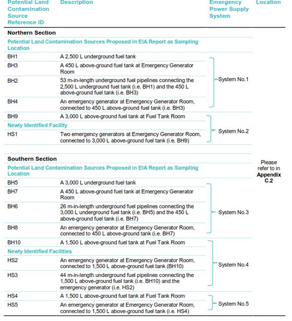
Follow-up site reconnaissance survey conducted in early 2018 has covered Fuel Tank Rooms and Emergency Generator Rooms in T2 building, including location BH1 – BH10 proposed in the EIA Report, as well as several concerned facilities identified in the as-built drawings. Those identified as potential land contamination sources are provided in Table 3.1. Newly identified potential sources thereafter annotated as HS. Locations please refer to the drawing for T2 building MCL/P132/EIA/11-014 with mark-up and associated zoom-in view in Appendix C.2.
Table 3.1: Potential Land Contamination Sources in T2 building
Northern Section of T2 Building
Emergency Power Supply System No.1 (BH1, BH2, BH3 and BH4)
This set of emergency power supply system comprises underground and above-ground section.
Underground section refers to the 2,500 L underground fuel tank containing diesel fuel (i.e. BH1) and its associated underground fuel pipelines 53 m in length (i.e. BH2). The 2,500 L underground fuel tank is fully encased in a 300 mm thick concrete chamber with manhole chamber at floor level for inspection purpose, while space between the tank and the concrete chamber is filled with sand. The quantity of fuel inside the tank is automatically monitored by level sensor. According to available maintenance record, the sensor has been malfunction since August 2016. Instead, manual monthly fuel level measurement and monitoring have been conducted by using dipstick since then. As no abnormality on fuel re-filling record have been observed, it is considered that there have been no loss of fuel as reported by the maintenance staff. The 53 meter-in-length underground pipeline is laid inside 100mm thick concrete trench backfilled with sand, located approximately 1.5 m below ground level.
Above-ground section refers to the 450 L above-ground fuel tank containing diesel fuel equipped with drip tray (i.e. BH 3) and the emergency generator (i.e. BH 4) both located at an Emergency Generator Room. Both fuel tank and generator are mounted on intact concrete floor with no oil stain. The above-ground fuel tank was surrounded by concrete curb. The fuel pipelines running through BH3 and BH4 are buried by sand inside a concrete and brick trench at floor level. Physical check of pipelines is possible by removing the chequer plate cover. System details are shown in drawings in Appendix E.1.
With regard to operation, this set of emergency power supply system (i.e. BH1 – BH4) has operated only for monthly test run (30-60 minutes for each run) since installation. The manhole chamber of underground fuel tank is checked monthly, while the underground fuel tank is re-filled approximately every 6 months.
For above-ground section (i.e. BH3 and BH4), taking into account of the facilities setup and operational schedule, with no record of fuel leakage, the potential of contamination is considered to be very unlikely; therefore, SI is considered not required for the 450 L above-ground fuel tank and the emergency generator. On the contrary, final inspection and record checking should be conducted right before decommissioning/ demolition of these facilities to ensure no contaminative activities during the period from now on till the decommissioning.
For underground section (i.e. BH1 and BH2), even the facilities are installed underground making physical inspection not possible, the high-standard engineering design (i.e. 300 mm thick concrete chamber of the fuel tank and 100 mm thick concrete trench of fuel pipelines), plus no record implying fuel leakage, the potential of contamination is anticipated to be unlikely. To confirm no potential land contamination taken place, an enhanced SI programme is designed for the concerned underground facilities. Therefore, the proposed SI locations in the EIA Report (i.e. BH1 and BH2) are still considered valid in this Supplementary CAP.
Emergency Power Supply System No.2 (BH9 and HS1)
The 3,000 L above-ground fuel tank with drip tray (i.e. BH9) at Fuel Tank Room containing diesel fuel, as recorded in the site reconnaissance survey in May 2017, is connected to two emergency generators located at the adjacent Emergency Generator Room (i.e. HS 1) which was newly identified in January 2018. Fuel pipelines running through the two facilities are either wall penetrating, or through concrete and brick trench filled with sand at floor level. Physical check of pipelines is possible by removing the chequer plate cover. Both of the concerned facilities (i.e. BH9 and HS1) being mounted on intact concrete floor with no oil stain. Bund wall is provided in the access of the fuel tank room. Reference to be made to drawings in Appendix E.2.
In terms of operation, this set of emergency power supply system has operated only for monthly test run (30-60 minutes for each run) since installation. The fuel tank is checked monthly and re-filled approximately every 6 months. The quantity of fuel inside the tank is monitored by level sensor while no sign of leakage being detected.
In view of facilities setup and operational schedule, with no record of fuel leakage, the potential of contamination is considered to be very unlikely; therefore, SI is considered not required for the above-ground fuel tank (i.e. BH9). For HS1, even though lubricating oil seepage during machine operation (i.e. Solely monthly test run) from engine flywheel/ engine body of one of the generators was recorded from June 2016 to March 2018 as shown in the available maintenance record, maintenance staff ensured that immediate clean-up of seepage was undertaken after every operation.
No cracks or oil stain on the intact concrete plinth underneath HS1 was observed according to site reconnaissance survey in January 2018. Based on the facility setup and site survey findings, it is considered that the contamination potential of seepage lubricating oil is very unlikely. (Refer to photo records in Appendix E.2). Hence, HS1 shared the same strategy with BH9 where SI works is considered not required. Instead, final inspection and record checking should be conducted right before decommissioning/ demolition of these facilities to ensure no contaminative activities during the period from now on till the decommissioning.
Southern Section of T2 Building
Emergency Power Supply System No.3 (BH5, BH6, BH7 and BH8)
This set of emergency power supply system comprises underground and above-ground section, shared similar component design to the Emergency Power Supply System No.1 (i.e. BH1 – BH4) at northern section.
Underground section refers to the 3,000 L underground fuel tank containing diesel fuel and its associated underground fuel pipelines 26 m in length, known as sampling locations BH5 and BH6 respectively. The 3,000 L underground fuel tank is fully encased in a 300 mm thick concrete chamber with a manhole chamber at floor level for inspection purpose, while space between the tank and the concrete chamber is filled with sand. The quantity of fuel inside the tank is automatically monitored by level sensor while no sign of leakage has been detected. The 26 meter-in-length underground pipeline is laid in 100mm thick concrete trench backfilled with sand.
Above-ground section refers to the 450 L above-ground fuel tank containing diesel fuel equipped with drip tray (i.e. BH7) and the emergency generator (i.e. BH8) both located at an Emergency Generator Room. Both fuel tank and generator are mounted on intact concrete floor with no oil stain.
The above-ground fuel tank was surrounded by concrete curb. The fuel pipelines running through BH7 and BH8 are laid inside sand filled concrete and brick trench at floor level. Physical check of pipelines is possible by removing the chequer plate cover. System details are shown in drawings in Appendix E.3.
In operational means, this set of emergency power supply system (i.e. BH5 – BH8) has operated only for monthly test run (30-60 minutes for each run) since installation. The manhole chamber of underground fuel tank is checked monthly, while the underground fuel tank is re-filled approximately every 6 months. Even seepage of lubricating oil from side cover of the emergency generator (i.e. BH8) had been recorded from Jun 2016 to Feb 2017 as shown in the available maintenance record, maintenance staff ensured that immediate clean-up of seepage was undertaken after every operation. The lubricating oil seepage problem was then solved in a comprehensive repair conducted in Feb 2017. Neither cracks nor oil stain was observed on the intact concrete plinth underneath BH8 in site reconnaissance survey in January 2018. Taking into account of facility setup and site survey observation, it is considered that the contamination potential of seepage lubricating oil is very unlikely. (Refer to photo record in Appendix E.3)
For above-ground section (i.e. BH7 and BH8), in view of the facilities setup and operational schedule, with no record of fuel leakage, the potential of contamination is considered to be very unlikely; therefore, SI is considered not required for the 450 L above-ground fuel tank and the emergency generator. On the contrary, final inspection and record checking should be conducted right before decommissioning/ demolition of these underground facilities to ensure no contaminative activities during the period from now on till the decommissioning.
For underground section (i.e. BH5 and BH6), even the facilities are installed underground making physical inspection not possible, the high-standard engineering design (i.e. 300 mm thick concrete chamber of the fuel tank and 100 mm thick concrete trench of fuel pipelines), plus no record implying fuel leakage, the potential of contamination is anticipated to be unlikely. To confirm no potential contamination taken place, an enhanced SI programme is designed for the concerned underground facilities. Therefore, the proposed SI locations in the EIA Report (i.e. BH5 and BH6) are still considered valid in this Supplementary CAP.
Emergency Power Supply System No. 4 (BH10, HS2 and HS3)
The system comprises the 1,500 L above-ground fuel tank containing diesel fuel at Fuel Tank Room equipped with drip tray (i.e. BH10) and a newly identified emergency generator at Emergency Generator Room (i.e. HS2) and the 44 m-in-length underground fuel pipelines running through the two facilities (i.e. HS3).
High-standard engineering design was found in facilities setup. Both above-ground facilities (i.e. BH10 and HS2) are mounted on intact concrete floor with no oil stain. Curb by builder is also provided in the Fuel Tank Room. The underground pipeline (i.e. HS3) is laid in concrete trench 1 m below ground level backfilled with mass/sand. System details are shown in drawings in Appendix E.4.
In terms of operational schedule, this set of emergency power supply system (i.e. BH10, HS2 and HS3) has operated only for monthly test run (30-60 minutes for each run) since installation. The fuel tank is checked monthly and re-filled approximately every 6 months. Level sensor is incorporated in the above-ground fuel tank to monitor the quantity of fuel while no sign of leakage being detected as illustrated in the available maintenance record.
Through taking into account the facilities setup and operational means, the potential of contamination from BH10 and HS2 are therefore considered to be very unlikely. SI is considered not required for the 1,500 L above-ground fuel tank (i.e. BH10) and the emergency generator (i.e. HS2). For the underground fuel pipelines (i.e. HS3), even physical inspection is not possible, the high-standard engineering design (i.e. concrete trench filled with mass/sand), plus no record implying leakage, supported that the potential of contamination is therefore considered to be unlikely. To confirm no potential contamination taken place, an enhanced SI programme is designed for the concerned underground facilities.
Emergency Power Supply System No. 5 (HS4 and HS5)
This set of emergency power supply system are newly identified in further as-built drawings review. The system comprises the 1,500 L above-ground fuel tank containing diesel fuel with drip tray at Fuel Tank Room (i.e. HS4) and the emergency generator at Emergency Generator Room (i.e. HS5). The fuel pipelines running through the two facilities are either wall penetrating or laid in a concrete and brick trench filled with sand at floor level. Physical check of pipelines is possible by removing the chequer plate cover. Both concerned facilities (i.e. HS4 and HS5) are mounted on intact concrete floor with no oil stain. Curb wall is also provided in the access of the fuel tank room. System details are shown in drawings in Appendix E.5.
In terms of operation, this set of emergency power supply system has operated only for monthly test run (30-60 minutes for each run) since installation. The fuel tank is checked monthly and re-filled approximately every 6 months. The quantity of fuel inside the tank is monitored by level sensor while no sign of leakage being detected. Based on the facility setup and site survey observation, it is considered that the contamination potential is very unlikely. (Refer to photo record in Appendix E.5)
Even though lubricating oil seepage from engine body and engine flywheel of the emergency generator (i.e. HS5) was recorded from January 2017 to March 2018 in reviewed maintenance record, maintenance staff ensured that immediate clean-up of seepage was undertaken after every operation. Neither cracks nor oil stain was observed on the intact concrete plinth underneath HS5 in site reconnaissance survey in February 2018. Taking into account of facility setup and site survey observation, it is considered that the contamination potential is very unlikely. (Refer to photo record in Appendix E.5)
In view of facilities setup and operational schedule, with no record of fuel leakage, the potential of contamination is considered to be very unlikely. Therefore, SI is considered not required for the 1,500 L above-ground fuel tank and the emergency generator. Instead, final inspection and record checking should be conducted right before decommissioning/ demolition of these facilities to ensure no contaminative activities during the period from now on till the decommissioning.
The completed site walkover checklist and the photographic records of concerned T2 building facilities are provided in Appendix B.6 and Appendix E respectively.
3.3
Identification of
Land Contamination Potential
Through consolidation of the findings from further as-built drawing review and the follow-up site reconnaissance survey, sampling location BH1, BH2, BH5, BH6 is still considered to be valid and to be included in the enhanced SI programme. The newly identified underground pipelines (i.e. HS3) of Emergency Power Supply System No. 4 at southern T2 building has also been included as enhancement of SI recommendation. Enhanced SI programme details will be presented in Section 4.3.
As described in Section 3.2.1, the proposed SI locations at the fuel tank room to the west of CAD antenna farm presented in the EIA Report (i.e. MCL/P132/EIA/11-015 in Appendix C.1) is still considered valid.
As presented in the EIA Report Table 3.3 and Section 4.2.2, petrol filling station covered by modification of existing North Runway was considered to have potential leakage/spillage of fuel which may cause land contamination concern. Therefore, site investigation was proposed for the location in sampling location BH11 to BH15. As for the latest programme in July 2018, the detailed design of the present North Runway modification is under review. The petrol filling station remains operating unless the final design being settled and thus confirm the necessity of filling station decommission. The sampling locations (i.e. BH11 – BH15) are still considered to be valid in this supplementary CAP. Subject to the result of detailed design review, site re-appraisal shall be conducted upon affirmation of the need for decommission of the petrol filling station. The proposed SI programme details will be presented in Section 4.1.3.
A summary of further site investigation recommended with reference to the observations of site reconnaissance survey conducted in third quarter of 2016 and May 2017 is presented in Table 3.2. Enhanced SI recommended for T2 building with reference to the observations of site reconnaissance survey conducted in early 2018 is presented in Table 3.3. All SI proposed to the latest available information at different stages are summarized in Table 3.4.
Table 3.2: Summary of Further Site Investigation Recommended
|
Potential Land Contamination Impact |
Need for Further Site Investigation |
Figure No. |
|
|
Fuel Tank Room to the West of CAD Antenna Farm |
A 900 L above-ground tank containing diesel fuel was found during the site reconnaissance survey. Potential leakage or spillage of fuel may cause land contamination concern. |
SI locations have been proposed during EIA stage and are still considered valid. SI will be conducted prior to the commencement of construction works at site. * |
Figure 3.1 and EIA drawing MCL/P132/EIA/11-015 as presented in Appendix C.1 |
|
Fuel Tank Room within T2 Building |
After consolidating latest information, the approach towards this facility is updated. Please refer to Potential Contamination Source Reference ID BH9 in Table 3.3.
|
||
|
Seawater Pump House |
No contaminative land use types were identified. |
No |
|
|
Switching Station |
During detailed design of the project, relocation of the switching station is no longer required. Therefore, site appraisal process for land contamination potential is considered not necessary. |
||
|
Pumping Station |
No contaminative land use types were identified. |
No |
|
|
Fire Training Facility |
A 10,000 L above-ground tank containing kerosene was found during the site reconnaissance survey. Potential leakage or spillage of fuel may cause land contamination concern. |
Yes, SI will be conducted prior to the commencement of construction works at site. * |
|
* The necessity of recommended Site Investigation (SI) is subject to review after the site re-appraisal to be conducted prior to commencement of SI works. Details is provided in Section 4.1.1 and Section 4.2.1 respectively.
Table 3.3: Summary of Enhanced Site Investigation Recommended for T2 building
|
Potential Land Contamination Impact |
Need for Enhanced Site Investigation |
Figure No. |
|
|
Northern Section |
|||
|
BH1
|
The 2,500 L underground fuel tank containing diesel fuel was reviewed through site reconnaissance survey and as-built drawings. Potential land contamination caused by leakage or spillage of fuel was considered to be unlikely.
|
SI locations have been proposed during EIA stage and are still considered valid. Enhanced SI will be conducted in decommissioning stage.
|
System details in Appendix E.1 and EIA drawing MCL/P132/EIA/11-014 with mark-up as presented in Appendix C.2
|
|
BH2 |
The 53 m-in-length underground fuel pipelines connecting the underground fuel tank (i.e. BH1) and the above-ground fuel tank (i.e. BH3) was reviewed through site reconnaissance survey and as-built drawings. Potential land contamination caused by leakage or spillage of fuel was considered to be unlikely.
|
SI location has been proposed during EIA stage and are still considered valid. Enhanced SI will be conducted in decommissioning stage. |
System details in Appendix E.1 and EIA drawing MCL/P132/EIA/11-014 with mark-up as presented in Appendix C.2
|
|
BH3* |
The 450 L above-ground fuel tank containing diesel fuel was reviewed through site reconnaissance survey and as-built drawings. Potential land contamination caused by leakage or spillage of fuel was considered to be very unlikely. |
No |
System details in Appendix E.1 and EIA drawing MCL/P132/EIA/11-014 with mark-up as presented in Appendix C.2
|
|
BH4* |
The emergency generator site was reviewed through site reconnaissance survey and as-built drawings. Potential land contamination caused by leakage or spillage of fuel was considered to be very unlikely. |
No |
System details in Appendix E.1 and EIA drawing MCL/P132/EIA/11-014 with mark-up as presented in Appendix C.2
|
|
BH9* |
The 3,000 L above-ground fuel tank containing diesel fuel was further reviewed through site reconnaissance survey and as-built drawings. The previously concerned potential land contamination caused by leakage or spillage of fuel was considered to be very unlikely. |
No |
System details in Appendix E.2 and EIA drawing MCL/P132/EIA/11-014 with mark-up as presented in Appendix C.2
|
|
HS1* |
The two emergency generators were identified in site reconnaissance survey. Potential land contamination caused by leakage or spillage of fuel was reviewed and considered to be very unlikely.
|
No |
System details in Appendix E.2 and EIA drawing MCL/P132/EIA/11-014 with mark-up as presented in Appendix C.2
|
|
Southern Section |
|||
|
BH5 |
The 3,000 L underground fuel tank containing diesel fuel was reviewed through site reconnaissance survey and as-built drawings. Potential land contamination caused by leakage or spillage of fuel was considered to be unlikely. |
SI location has been proposed during EIA stage and are
still considered valid. Enhanced SI will be conducted in decommissioning stage. |
System details in Appendix E.3 and EIA drawing MCL/P132/EIA/11-014 with mark-up as presented in Appendix C.2
|
|
BH6 |
The 26 m-in-length underground fuel pipelines connecting the underground fuel tank (i.e. BH5) and the above-ground fuel tank (i.e. BH7) was reviewed through site reconnaissance survey and as-built drawings. Potential land contamination caused by leakage or spillage of fuel was considered to be unlikely. |
SI location has been proposed during EIA stage and are still considered valid. Enhanced SI will be conducted in decommissioning stage. |
System details in Appendix E.3 and EIA drawing MCL/P132/EIA/11-014 with mark-up as presented in Appendix C.2
|
|
BH7* |
The 450 L above-ground fuel tank containing diesel fuel was reviewed through site reconnaissance survey and as-built drawings. Potential land contamination caused by leakage or spillage of fuel was considered to be very unlikely. |
No |
System details in Appendix E.3 and EIA drawing MCL/P132/EIA/11-014 with mark-up as presented in Appendix C.2
|
|
BH8* |
The emergency generator was reviewed through site reconnaissance survey and as-built drawings. Potential land contamination caused by leakage or spillage of fuel was considered to be very unlikely. |
No |
System details in Appendix E.3 and EIA drawing MCL/P132/EIA/11-014 with mark-up as presented in Appendix C.2
|
|
BH10* |
The 1,500 L above-ground fuel tank containing diesel fuel was reviewed through site reconnaissance survey and as-built drawings. Potential land contamination caused by leakage or spillage of fuel was considered to be very unlikely. |
No |
System details in Appendix E.4 and EIA drawing MCL/P132/EIA/11-014 with mark-up as presented in Appendix C.2
|
|
HS2* |
The emergency generator was identified in site reconnaissance survey. Potential land contamination caused by leakage or spillage of fuel was reviewed and considered to be very unlikely. |
No |
System details in Appendix E.4 and EIA drawing MCL/P132/EIA/11-014 with mark-up as presented in Appendix C.2
|
|
HS3 |
The 44 m-in-length underground fuel pipelines connecting the above-ground fuel tank (i.e. HS4) and the emergency generator (i.e. HS5) were identified in site reconnaissance survey. Potential land contamination caused by leakage or spillage of fuel was reviewed and considered to be unlikely. |
Yes, Enhanced SI in decommissioning stage. |
System details in Appendix E.4 and EIA drawing MCL/P132/EIA/11-014 with mark-up as presented in Appendix C.2
|
|
HS4* |
The 1,500 L above-ground fuel tank containing diesel fuel was identified in site reconnaissance survey. Potential land contamination caused by leakage or spillage of fuel was reviewed and considered to be very unlikely. |
No |
System details in Appendix E.5 and EIA drawing MCL/P132/EIA/11-014 with mark-up as presented in Appendix C.2
|
|
HS5* |
The emergency generator was identified in site reconnaissance survey. Potential land contamination caused by leakage or spillage of fuel was reviewed and considered to be very unlikely. |
No |
System details in Appendix E.5 and EIA drawing MCL/P132/EIA/11-014
with mark-up as presented in Appendix C.2 |
* Subject to final inspection and record checking conducted right before decommissioning/ demolition of the facility to ensure no contaminative activities during the period from now on till the decommissioning.
Table 3.4: Summary of All Site Investigation
|
Potential Land Contamination Source Reference ID |
Location |
Source Description |
Site Investigation strategy |
|
BH11, BH12, BH13, BH14, BH15 |
Airside Petrol Filling Station |
The underground fuel storage tanks and the petrol dispensers |
As in EIA stage * |
|
BH16, BH17 |
Fuel Tank Room to the West of CAD Antenna Farm |
The 900 L above-ground tank containing diesel fuel |
As in EIA stage** |
|
BH18 |
Fire Training Facility |
The 10,000 L above-ground tank containing kerosene |
As additional site investigation** |
|
BH1 |
Northern Section of T2 |
The 2,500 L underground fuel tank containing diesel fuel |
As enhanced site investigation |
|
BH2 |
Northern Section of T2 |
The 53 m-in-length underground fuel pipelines connecting the underground fuel tank (i.e. BH1) and the above-ground fuel tank (i.e. BH3) |
As enhanced site investigation |
|
BH5 |
Southern Section of T2 |
The 3,000 L underground fuel tank containing diesel fuel |
As enhanced site investigation |
|
BH6 |
Southern Section of T2 |
The 26 m-in-length underground fuel pipelines connecting the underground fuel tank (i.e. BH5) and the above-ground fuel tank (i.e. BH7) |
As enhanced site investigation |
|
HS3 |
Southern Section of T2 |
The 44 m-in-length underground fuel pipelines connecting the above-ground fuel tank (i.e. HS4) and the emergency generator (i.e. HS5) |
As enhanced site investigation |
* The necessity of recommended Site Investigation (SI) shall be subject to the result of detailed design review. Details are provided in Section 4.1.3.
**The necessity of recommended Site Investigation (SI) shall be subject to review after the site re-appraisal prior to commencement of SI works. Details are provided in Section 4.1.1 and Section 4.2.1 respectively.
4
Proposed Site Investigation Works
4.1
Site Investigation Works Proposed in EIA Stage
4.1.1
Fuel Tank Room to the West of CAD Antenna Farm
As mentioned in Section 3.2.1, a 900 L above-ground tank containing diesel fuel was found during the site reconnaissance survey. A total of two boreholes (i.e. BH16 and BH17) were proposed in the EIA drawing MCL/P132/EIA/11-015 as presented in Appendix C.1 for the above-ground fuel tank. The proposed SI locations were still considered valid in this Supplementary CAP.
It should be noted that site re-appraisal will be conducted prior to commencement of SI works to ascertain initial contamination evaluation of the area and review the necessity of site investigation works proposed in the aforementioned submission. The findings of the re-appraisal will be documented appropriately and seek EPD agreement prior to the commencement of site investigation works, if require. Subsequent sampling and testing works will be conducted prior to commencement of any construction works at this area.
4.1.2
T2 Building
Further to the elaboration in Section 3.2.5, SI locations proposed in EIA stage are reviewed after consolidating site reconnaissance survey findings, as-built drawings and on-site personnel interview. SI approach of T2 Building facilities are proposed and presented in Table 3.3. Associated enhanced SI programme are elaborated in Section 4.3.
4.1.3
Airside Petrol Filling Station
Further to Section 3.3, a total of five boreholes (i.e. BH11 to BH15) were proposed for the airside petrol filling station and the tentative sampling locations are shown in the EIA drawing MCL/P132/EIA/11-015 as presented in Appendix C.1. Since there is no change in land use, the proposed SI locations were still considered valid in this Supplementary CAP.
Subject to the result of detailed design review (as in July 2018), site re-appraisal shall be conducted upon affirmation of the need for decommission of the petrol filling station. The findings of the re-appraisal (if any) will be documented appropriately and seek EPD agreement prior to the commencement of site investigation works.
4.2
Additional Site
Investigation Works
4.2.1
Fire Training Facility
As mentioned in Section 3.2.4, the fire training facility is not identified as one of the potential contaminative land use types as given in Table 2.3 of the Practice Guide. A 10,000 L above-ground tank containing kerosene fuel was found during the site reconnaissance survey, hence SI is proposed for this above-ground kerosene tank.
One new borehole (BH18) is proposed at the 10,000 L above-ground fuel tank inside the fire training facility. The tentative sampling location is shown in Figure 4.1.
To ascertain contamination evaluation of this facility and review the necessity of additional site investigation works proposed, site re-appraisal will be conducted prior to commencement of SI works. The findings of the re-appraisal will be documented appropriately and seek EPD agreement prior to the commencement of site investigation works, if require. Subsequent sampling and testing works will be conducted prior to commencement of any construction works at this area.
4.3
Enhanced Site
Investigation Works for T2 Building
As mentioned in Section 3.2.5, enhanced SI is recommended for the underground facilities in T2 building. Sampling locations included in enhanced SI are provided in Table 3.4.
Four sampling locations, BH1, BH2, BH5 and BH6 proposed in the EIA drawing MCL/P132/EIA/11-014 are still considered valid, while sampling location HS3 for the 44 m-in-length underground fuel pipelines at southern section is newly proposed as shown in marked-up EIA drawing MCL/P132/EIA/11-014 in Appendix C.2. Sampling and testing works of the enhanced SI will be conducted along with decommissioning/demolition of concerned facilities.
4.4
Sampling Details
4.4.1
Sampling and Testing Plan
The sampling and testing plan for the airside petrol filling station, the fuel tank room to the West of CAD Antenna Farm and Fire Service Facility, including sampling locations and depths, is recommended in accordance with the EPD’s Practice Guide for Investigation and Remediation of Contaminated Land as shown in Table 4.2.
Enhanced sampling and testing plan for concerned underground facilities of T2 Building, including sampling location and depths, are presented in Table 4.3. The exact locations and depths for sand and soil sampling shall be determined by on-site land contamination specialist to suit the actual site condition during site investigation.
4.4.2
Sampling Method and Depth of Sampling
All soil boring/ excavation and sampling should be supervised by a land contamination specialist.
At each sampling location/depth, sufficient quantity of soil/sand sample (as specified by the laboratory) should be taken. All soil/sand samples should be uniquely labelled. Backup samples should be retained and stored at 0-4 ºC in laboratory.
Borehole and Trial Pit Sampling for Airside Petrol Filling Station, West of CAD Antenna Farm and Fire Service Facility
Borehole sampling is designated to sampling plan for the airside petrol filling station, fuel tank room to the West of CAD Antenna Farm and Fire Service Facility.
Borehole should be undertaken by means of dry rotary drilling method, i.e. without the use of flushing medium, to prevent cross-contamination during sampling. For safety reasons, an inspection pit should be excavated down to 1.5 m below ground surface (bgs) to inspect for underground utilities at the proposed borehole location. Disturbed soil samples should be collected at depth of 0.5 m bgs. Soil boring using drill rigs should then be performed from depth of 1.5 m bgs to the maximum boring depth. Undisturbed U100/U76 soil samples should be collected at 1.5 m and 3.0 m bgs as well as above groundwater level. Groundwater samples should be collected at the level of groundwater (if encountered).
Where borehole drilling is not possible due to site constraints (e.g. insufficient head room or accessibility of drilling rigs), sampling using trial pit methods will be adopted. For trial pit methods, disturbed soil samples, using stainless steel hand tools, will be taken at 0.5 m, 1.5 m and 3.0 m bgs in order to delineate the vertical profile of contamination.
Appropriate safety precautionary measures such as shoring support, stepping/sloping of sides will be implemented for the excavation of trial pit exceeding 1.2 m, with reference to the “Practice Guide for Investigation and Remediation of Contaminated Land” issued by EPD and “Guide to Trench Excavations (Shoring Support and Drainage Measures)” issued by Utilities Technical Liaison Committee of Highway Department and Geotechnical Engineering Office of Civil Engineering Department.
Grab Sampling for Concerned Underground Facilities of T2 Building
Grab sampling is proposed for the locations listed in Table 4.3 as Enhanced Sampling and Testing plan. Sand and soil samples shall be grabbed manually during decommissioning/ demolition process of concerned underground pipeline trench and fuel tanks. The whole sampling process shall be under the supervision of on-site Contamination Specialist.
Sampling Selection of Underground Fuel Tank
Sand and soil samples should be collected as follows,
· Sand samples should be collected at 0.5 m, 1.5 m and bottom level inside the concrete chamber of underground fuel tank;
· Soil sample should be collected right underneath concrete chamber of underground fuel tank.
Sampling Selection of Underground Fuel Pipelines
Sand and soil samples should be collected as follows,
· Sand samples should be taken at every curvature of pipelines inside the concrete trench;
· Additional sampling points inside the concrete trench are set depending on length of pipeline segment (from curvature/connection to curvature):
° If pipeline segment is ≤10 m, additional sample is considered not required;
° If pipeline segment is >10 m and ≤20 m, one sample shall be taken at segment mid-point;
° If pipeline segment is >20 m and ≤30 m, samples shall be collected at 2 points which are evenly spaced with each other and segment ends.
· Soil samples should be taken right underneath concrete trench at every curvature.
Sampling point annotation and indicative sampling point locations are illustrated in Appendix F and Table 4.1.
Table 4.1: Sampling Point Annotation of Underground Fuel Pipelines
|
Proposed Sampling Locations |
Annotation of Sampling Point |
Type of Sampling Point (Curvature/ Additional) |
Figure No. |
|
BH2 |
BH2-S1 |
Curvature |
|
|
BH2-S2 |
Curvature |
||
|
BH2-S3 |
Curvature |
||
|
BH2-S4 |
Additional |
||
|
BH2-S5 |
Additional |
||
|
BH2-S6 |
Curvature |
||
|
BH2-S7 |
Additional |
||
|
BH6 |
BH6-S1 |
Curvature |
|
|
BH6-S2 |
Additional |
||
|
BH6-S3 |
Additional |
||
|
BH6-S4 |
Curvature |
||
|
HS3-S1 |
Curvature |
||
|
HS3-S2 |
Additional |
||
|
HS3-S3 |
Curvature |
||
|
HS3-S4 |
Curvature |
||
|
HS3-S5 |
Additional |
||
|
HS3-S6 |
Additional |
||
|
HS3-S7 |
Curvature |
Table 4.2: Sampling and Testing Plan for Airside Petrol Filling Station, the fuel tank room to the West of CAD Antenna Farm and Fire Service Facility
|
Proposed Sampling Locations |
Sample Matrix3 |
Parameters to be Tested4 |
Rationale of Sampling |
|||||||||
|
Heavy Metals |
PCRs5 |
VOCs5 |
SVOCs5
|
|||||||||
|
BH111 |
Soil |
0.5 m, 1.5 m, 3.0 m bgs |
Full list |
√ |
√ |
√ |
Assess potential land contamination impact from petrol filling activities |
|||||
|
GW |
If present^ |
Mercury only |
√ |
√ |
√ |
|||||||
|
BH121 |
Soil |
0.5 m, 1.5 m, 3.0 m bgs |
Full list |
√ |
√ |
√ |
Assess potential land contamination impact from petrol filling activities |
|||||
|
GW |
If present^ |
Mercury only |
√ |
√ |
√ |
|||||||
|
BH131 |
Soil |
0.5 m, 1.5 m, 3.0 m below the base of underground fuel tank |
Full list |
√ |
√ |
√ |
Assess potential land contamination impact from underground fuel tanks |
|||||
|
GW |
If present^ |
Mercury only |
√ |
√ |
√ |
|||||||
|
BH141 |
Soil |
0.5 m, 1.5 m, 3.0 m below the base of underground fuel tank |
Full list |
√ |
√ |
√ |
Assess potential land contamination impact from underground fuel tanks |
|||||
|
GW |
If present^ |
Mercury only |
√ |
√ |
√ |
|||||||
|
BH151 |
Soil |
0.5 m, 1.5 m, 3.0 m below the base of underground fuel tank |
Full list |
√ |
√ |
√ |
Assess potential land contamination impact from underground fuel tanks |
|||||
|
GW |
If present^ |
Mercury only |
√ |
√ |
√ |
|||||||
|
Fuel Tank Room to the West of CAD Antenna Farm#, ** |
||||||||||||
|
BH162 |
Soil |
Full list |
√ |
√ |
√ |
Assess potential land contamination impact from the fuel tank |
||||||
|
GW |
If present^ |
Mercury only |
√ |
√ |
√ |
|||||||
|
BH172 |
Soil |
0.5 m, 1.5 m, 3.0 m bgs |
Full list |
√ |
√ |
√ |
Assess potential land contamination impact from the fuel tank |
|||||
|
GW |
If present^ |
Mercury only |
√ |
√ |
√ |
|||||||
|
Fire Training Facility** |
||||||||||||
|
BH182 |
Soil |
0.5 m, 1.5 m, 3.0 m bgs |
Full list |
√ |
√ |
√ |
Assess potential land contamination impact from the above-ground fuel tank |
|||||
|
GW |
If present^ |
Mercury only |
√ |
√ |
√ |
|||||||
Remarks:
1Exact sampling locations will be identified on-site after decommissioning of petrol filling station.
2Exact sampling locations will be identified on site after the removal of the fuel tank.
3 bgs = Below Ground Surface; GW = groundwater.
4ü = testing proposed.
5 PCRs = Petroleum Carbon Ranges; VOCs = Volatile Organic Chemicals; SVOCs = Semi-volatile Organic Chemicals;
^ Samples will only be collected if groundwater is encountered during SI works.
#The sampling and testing plan for Airside Petrol Filling Station and fuel tank room to the West of CAD Antenna Farm are extracted from Table 4.2 of the Approved CAP.
* Testing protocol shall be reviewed subject to the result of detailed design review. Details are provided in Section 4.1.3.
**Testing protocol shall be reviewed after the site re-appraisal prior to commencement of SI works. Details are provided in Section 4.1.1 and Section 4.2.1 respectively.
Table 4.3: Enhanced Sampling and Testing Plan for T2 Building
|
Proposed Sampling Locations |
Sample Matrix |
Sampling Point Annotation |
Parameters to be Tested1
& 2 |
Rationale of Sampling |
|||||||
|
Heavy
Metals |
PCRs3 |
VOCs3 |
SVOCs3 |
||||||||
|
Northern Section |
|||||||||||
|
BH14 |
Sand5 |
0.5 m, 1.5 m bgs6and bottom level inside the concrete
chamber |
/ |
Lead only |
√ |
BTEX7 and MTBE8 |
PAHs9 |
Confirm no diesel leakage from underground fuel tank |
|||
|
|
Soil |
Right underneath concrete chamber |
/ |
Lead only |
√ |
BTEX7 and MTBE8 |
PAHs9 |
Confirm no leaked diesel (if any) penetrate the concrete chamber |
|||
|
BH24 |
Sand5 |
At the level of fuel pipelines |
BH2S1 - BH2S7 |
Lead only |
√ |
BTEX7 and MTBE8 |
PAHs9 |
Confirm no diesel leakage from underground fuel pipelines |
|||
|
|
Soil |
Right underneath concrete/brick trench |
BH2S1, BH2S2, BH2S3,
BH2S6 |
Lead only |
√ |
BTEX7 and MTBE8 |
PAHs9 |
Confirm no leaked diesel (if any) penetrate the concrete /brick trench |
|||
|
Southern Section |
|||||||||||
|
BH54 |
Sand5 |
0.5 m, 1.5 m bgs6 and bottom level inside the concrete
chamber |
/ |
Lead only |
√ |
BTEX7 and MTBE8 |
PAHs9 |
Confirm no diesel leakage from underground fuel tank |
|||
|
|
Soil |
Right underneath concrete chamber |
/ |
Lead only |
√ |
BTEX7 and MTBE8 |
PAHs9 |
Confirm no leaked diesel (if any) penetrate the concrete chamber |
|||
|
BH64 |
Sand5 |
At the level of fuel pipelines |
BH6S1 - BH6S4 |
Lead only |
√ |
BTEX7 and MTBE8 |
PAHs9 |
Confirm no diesel leakage from underground fuel pipelines |
|||
|
|
Soil |
Right underneath concrete/brick trench |
BH6S1, BH6S4 |
Lead only |
√ |
BTEX7 and MTBE8 |
PAHs9 |
Confirm no leaked diesel (if any) penetrate the concrete /brick trench |
|||
|
HS34 |
Sand5 |
At the level of fuel pipelines |
HS3S1 - HS3S7 |
Lead only |
√ |
BTEX7 and MTBE8 |
PAHs9 |
Confirm no diesel leakage from underground fuel pipelines |
|||
|
|
Soil |
Right underneath concrete/brick trench |
HS3S1, HS3S3, HS3S4, HS3S7 |
Lead only |
√ |
BTEX7 and MTBE8 |
PAHs9 |
Confirm no leaked diesel (if any) penetrate the concrete /brick trench |
|||
Remarks:
1 ü = testing proposed.
2 Having reviewed the
potentially polluting activities of the site (use of diesel fuel) and S2.4.3 of
Practice Guide, it is recommended to analyse the key COCs (i.e.
Lead, PCRs, BTEX, MTBE and PAHs) of “Petrol Filling Station” which is the most
relevant land use type for the case of T2. The concerned diesel tanks and
pipelines are used for storage and transfer of diesel fuel only and only diesel
fuel is used for the generator. It is noted BTEX, MTBE and Lead present in gasoline
but unlikely to be found in diesel fuel.
3 PCRs = Petroleum Carbon
Ranges; VOCs = Volatile Organic Chemicals; SVOCs = Semi-volatile Organic Chemicals;
4 Exact sampling locations will be
identified on site during the removal of sand/soil during fuel tank and
pipelines decommissioning/ demolition.
5 All sand samples will be collected
within the concrete chamber or concrete/brick trench.
6 bgs = Below Ground Surface.
7 BTEX = Benzene, Toluene, Ethylbenzene, and
Xylenes.
8 MTBE = Methyl
Tert-Butyl Ether.
9 Polyaromatic
hydrocarbons (PAHs) in the RBRGs include, acenaphthene, acenaphthylene,
anthracene, benzo(a)anthracene, benzo(a)pyrene, benzo(b)fluoranthene, benzo(g,h,i)perylene,
benzo(k)fluoranthene, chrysene, dibenzo(a,h)anthracene,
fluoranthene, fluorene, indeno(1,2,3-cd)pyrene,
naphthalene, phenanthrene and pyrene.
4.4.3
Strata Logging
Strata logging for boreholes should be undertaken during the course of drilling/digging and sampling by a qualified geologist. The logs should include the general stratigraphic description, depth of soil sampling, sample notation and level of groundwater (if encountered). The presence of rocks/boulders/cobbles and foreign materials such as metals, wood and plastics should also be recorded.
4.4.4
Free Product and Groundwater Level Measurement
The thickness of any free product and ground water level (if present) at sampling locations should be measured with an interface probe. The free product (if encountered in sufficient amounts) should be collected for laboratory analysis to determine the composition.
4.4.5
Groundwater Sampling
It is proposed to collect groundwater samples if groundwater is encountered at the sampling locations.
For each proposed borehole sampling location, a groundwater sampling well should be installed into the boreholes if groundwater is encountered or agreed by the land contamination specialist. A typical configuration of a groundwater monitoring well is shown in Appendix D. After installation of the monitoring wells, the depth to water table at all monitoring wells should be measured at the same time with an interface probe in order to delineate the groundwater table contours at the subject site. Well developments (approximately five well volumes) should be carried out to remove silt and drilling fluid residue from the wells. The wells should then be allowed to stand for a day to permit groundwater conditions to equilibrate. Groundwater level and thickness of free product layer, if present, should be measured at each well before groundwater samples are taken.
Prior to groundwater sampling, the monitoring wells should be purged (at least three well volumes) to remove fine-grained materials and to collect freshly refilled representative groundwater samples.
After purging, one groundwater sample should then be collected at each well using Teflon bailer and decanted into appropriate sample vials or bottles in a manner that minimises agitation and volatilization of volatile organic chemicals (VOCs) from the samples. All samples should be uniquely labelled.
If required, one groundwater sample at each trial pit using Teflon bailer should be taken if groundwater is encountered. The groundwater should only be taken after all required soil samples at the sampling location have been collected. The trial pit should be pumped to near dry and allowed to stand for 24 hours before sampling.
If groundwater sample is collected in trial pit, the trial pit should be enclosed on four sides by impervious sheeting at the end of each day to avoid potential contamination such as dust from the surrounding environment during groundwater sampling.
Immediately after collection, groundwater samples should be transferred to new, clean, laboratory-supplied glass jars for sample storage/transport. The sampling glass jars should be of “darkened” type. Groundwater samples should be placed in the glass jars with zero headspace and promptly sealed with a septum-lined cap. Immediately following collection, samples should be placed in ice chests, cooled and maintained at a temperature of about 4 ºC until delivered to the analytical laboratory.
4.4.6
Sample Size and Decontamination Procedures
All equipment in contact with the ground should be thoroughly decontaminated between each excavation, drilling and sampling event to minimise the potential for cross contamination. The equipment (including drilling pit, digging tools and soil/sand/groundwater samplers) should be decontaminated by steam cleaning or high-pressure hot water jet, then washed by phosphate-free detergent and finally rinsed by distilled / deionised water.
Prior to sampling, the laboratory responsible for analysis should be consulted on the particular sample size and preservation procedures that are necessary for each chemical analysis.
The sample containers should be laboratory cleaned, sealable, water-tight, made of glass or other suitable materials with aluminium or Teflon-lined lids, so that the container surface will not react with the sample or adsorb contaminants. No headspace should be allowed in the containers which contain samples to be analysed for VOCs, Petroleum Hydrocarbon Ranges or other volatile chemicals.
The containers should be marked with the sampling location codes and the depths at which the samples were taken. If the contents are hazardous, this should be clearly marked on the container and precautions taken during transport. Samples should be stored at between 0-4 ºC but never frozen. Samples should be delivered to laboratory within 24 hours of the samples being collected and analysed within the respective retention period but should not be more than 10 days.
4.4.7
Quality Assurance / Quality Control Procedures
Quality Assurance / Quality Control (QA/QC) samples should be collected with the following frequency during the SI. Chain of Custody protocol should be adopted.
● One equipment blank per 20 samples for full suite analysis;
● One field blank per 20 samples for full suite analysis;
● One duplicate sample per 20 samples for full suite analysis; and
● One trip blank per trip for the analysis of volatile parameters.
4.4.8
Health and
Safety
The specific safety measures to be taken depend on the nature and content of contamination, the site conditions and the regulations related to site safety requirements. Workers Compensation Insurance and third party insurance must be provided for the SI.
Extreme care should be exercised when toxic gases or other hazardous materials are encountered. Any abnormal conditions found shall be reported immediately to the safety officer and the land contamination specialist.
The SI contractor shall establish and maintain a Health and Safety Plan before commencement of the SI that will include the following:
● Instruction of works on work procedures, safe practices, emergency duties, and applicable regulations;
● Regularly scheduled meetings of the workers in which the possible hazards, problems of the job, and related safe practices are emphasised and discussed;
● Good housekeeping practices; and
● Availability of and instruction in the location, use and maintenance of personal protective equipment.
The SI Contractor shall maintain equipment and supplies reasonably required in an emergency, including lifesaving, evacuation, rescue and medical equipment in good working order and condition at all times. The SI Contractor shall use all reasonable means to control and prevent fires and explosions, injury to personnel and damage to equipment of property. Without limiting the foregoing, the SI Contractor shall:
● Maintain proper safety devices and barriers to minimise hazards during performance of the work;
● Prohibit smoking and open flames and the carrying of matches and lighters;
● Develop and maintain a written emergency plan applicable to the work site;
● Maintain equipment in good operating condition and have emergency and first aid equipment ready for immediate use, where applicable;
● Conduct equipment tests to ensure that equipment is properly placed and in good operating condition, and that workers are able to respond to emergency situations;
● Require all workers employed or retained by the Contractor, or a subcontractor, to at all time wear clothing suitable for existing work, weather and environmental conditions;
● Require the site personnel to wear respirator and gloves for vapour exposure protection, if necessary; and
● Ensure all site staff members wear safety helmet and protective boots.
5
Proposed Laboratory Analysis
5.1
Airside Petrol Filling Station, Fuel Tank Room to the West
of CAD Antenna Farm and Fire Training Facility
Laboratory analysis is proposed for the soil and groundwater (if any) samples collected at airside petrol filling station, the fuel tank room to the west of CAD antenna farm and fire training facility in order to screen the presence of potential contaminants that are of concerns as shown in Table 4.2.
Table 5.1 summarises the parameters, the minimum requirement of the reporting limits and reference methods for the laboratory analyses of soil and groundwater samples.
Table 5.1: Parameters, Detection Limits and Reference Methods for Laboratory Analysis of Samples Collected at Airside Petrol Filling Station, Fuel Tank Room to the West of CAD Antenna Farm and Fire Training Facility
|
Parameter |
Soil |
Groundwater |
|
|||
|
Detection Limit (mg/kg) or other stated |
Reference Method |
Detection
Limit (µg/L) or other stated |
|
Reference Method |
||
|
VOCs |
|
|
||||
|
Acetone |
50 |
USEPA 8260 or similar method* |
500 |
USEPA 8260 or similar method* |
|
|
|
Benzene |
0.2 |
5 |
|
|||
|
Bromodichloromethane |
0.1 |
5 |
|
|||
|
2-Butanone |
5 |
50 |
|
|||
|
Chloroform |
0.04 |
5 |
|
|||
|
Ethylbenzene |
0.5 |
5 |
|
|||
|
Methyl tert-Butyl Ether |
0.5 |
5 |
|
|||
|
Methylene Chloride |
0.5 |
50 |
|
|||
|
Styrene |
0.5 |
5 |
|
|||
|
Tetrachloroethene |
0.04 |
5 |
|
|||
|
Toluene |
0.5 |
5 |
|
|||
|
Trichloroethene |
0.1 |
5 |
|
|||
|
Xylenes (Total) |
2 |
20 |
|
|||
|
SVOCs |
|
|
||||
|
Acenaphthene |
0.5 |
USEPA 8270D or similar method* |
2 |
USEPA 8270D or similar method* |
|
|
|
Acenaphthylene |
0.5 |
2 |
|
|||
|
Anthracene |
0.5 |
2 |
|
|||
|
Benzo(a)anthracene |
0.5 |
N/A |
|
|||
|
Benzo(a)pyrene |
0.5 |
N/A |
|
|||
|
Benzo(b)fluoranthene |
0.5 |
1 |
|
|||
|
Benzo(g,h,i)perylene |
0.5 |
N/A |
|
|||
|
Benzo(k)fluoranthene |
0.5 |
N/A |
|
|||
|
Bis-(2-Ethylhexyl)phthalate |
5 |
N/A |
|
|||
|
Chrysene |
0.5 |
1 |
|
|||
|
Dibenzo(a,h)anthracene |
0.5 |
N/A |
|
|||
|
Fluoranthene |
0.5 |
2 |
|
|||
|
Fluorene |
0.5 |
2 |
|
|||
|
Hexachlorobenzene |
0.2 |
4 |
|
|||
|
Indeno(1,2,3-cd)pyrene |
0.5 |
N/A |
|
|||
|
Naphthalene |
0.5 |
2 |
|
|||
|
Phenanthrene |
0.5 |
2 |
|
|||
|
Phenol |
0.5 |
N/A |
|
|||
|
Pyrene |
0.5 |
2 |
|
|||
|
Metals |
|
|
||||
|
Antimony |
1 |
USEPA 6020 or similar method* |
N/A |
USEPA 6020 or similar method* |
|
|
|
Arsenic |
1 |
N/A |
|
|||
|
Barium |
1 |
N/A |
|
|||
|
Cadmium |
0.2 |
N/A |
|
|||
|
Chromium III |
1 |
N/A |
|
|||
|
Chromium VI |
1 |
N/A |
|
|||
|
Cobalt |
1 |
N/A |
|
|||
|
Copper |
1 |
N/A |
|
|||
|
Lead |
1 |
N/A |
|
|||
|
Manganese |
1 |
N/A |
|
|||
|
Mercury |
0.05 |
0.5 |
|
|||
|
Molybdenum |
1 |
N/A |
|
|||
|
Nickel |
1 |
N/A |
|
|||
|
Tin |
1 |
N/A |
|
|||
|
Zinc |
1 |
N/A |
|
|||
|
Petroleum Carbon Ranges |
|
|
||||
|
C6 - C8 |
5 |
USEPA 8260B / 8015 or similar method* |
20 |
USEPA 8260B / 8015 or similar method* |
|
|
|
C9 - C16 |
200 |
500 |
|
|||
|
C17 - C35 |
500 |
500 |
|
|||
Remark:
*Alternative testing methods with accreditation by HOKLAS or its Mutual Recognition Arrangement partner are also acceptable.
N/A - Not Available.
5.2
T2 Building
Laboratory analysis is proposed for the sand and soil samples collected at underground facilities in T2 building in order to ensure no potential contaminants present that are of concerns as shown in Table 4.3.
Table 5.2 summarises the parameters, the minimum requirement of the reporting limits and reference methods for the laboratory analyses of soil/sand samples.
Table 5.2: Parameters, Detection Limits and Reference Methods for Laboratory Analysis of Samples Collected at T2 Building
|
Parameter |
Soil/Sand |
Groundwater |
||
|
|
Detection Limit (mg/kg) or other stated |
Reference Method |
Detection Limit (µg/L) or other stated |
Reference Method |
|
VOCs |
|
|||
|
Benzene |
0.2 |
USEPA 8260 or similar method* |
5 |
USEPA 8260 or similar method* |
|
Ethylbenzene |
0.5 |
5 |
||
|
Methyl tert-Butyl Ether |
0.5 |
5 |
||
|
Toluene |
0.5 |
5 |
||
|
Xylenes (Total) |
2 |
20 |
||
|
SVOCs |
|
|||
|
Acenaphthene |
0.5 |
USEPA 8270D or similar method* |
2 |
USEPA 8270D or similar method* |
|
Acenaphthylene |
0.5 |
2 |
||
|
Anthracene |
0.5 |
2 |
||
|
Benzo(a)anthracene |
0.5 |
N/A |
||
|
Benzo(a)pyrene |
0.5 |
N/A |
||
|
Benzo(b)fluoranthene |
0.5 |
1 |
||
|
Benzo(g,h,i)perylene |
0.5 |
N/A |
||
|
Benzo(k)fluoranthene |
0.5 |
N/A |
||
|
Chrysene |
0.5 |
1 |
||
|
Dibenzo(a,h)anthracene |
0.5 |
N/A |
||
|
Fluoranthene |
0.5 |
2 |
||
|
Fluorene |
0.5 |
2 |
||
|
Indeno(1,2,3-cd)pyrene |
0.5 |
N/A |
||
|
Naphthalene |
0.5 |
2 |
||
|
Phenanthrene |
0.5 |
2 |
||
|
Pyrene |
0.5 |
2 |
||
|
Metals |
|
|||
|
Lead |
1 |
USEPA 6020 or similar method* |
N/A |
USEPA 6020 or similar method* |
|
Petroleum Carbon Ranges |
|
|||
|
C6 - C8 |
5 |
USEPA 8260B / 8015 or similar method* |
20 |
USEPA 8260B / 8015 or similar method* |
|
C9 - C16 |
200 |
500 |
||
|
C17 - C35 |
500 |
500 |
||
Remark:
*Alternative testing methods with accreditation by HOKLAS or its Mutual Recognition Arrangement partner are also acceptable.
N/A - Not Available.
5.3
Interpretation
of Results
The soil, groundwater and sand samples collected from the proposed SI works will be compared with RBRGs as stipulated in Table 2.1 and Table 2.2 of the Guidance Manual.
The RBRGs are developed based on a risk assessment approach to suit the local environmental conditions and community needs in Hong Kong. Decisions on contaminated soil and groundwater (if any) remediation are based on the nature and extent of the potential risks that are posed to human receptors as a result of exposure to chemicals in the soil and/or groundwater. RBRGs are developed for four different land use scenarios reflecting the typical physical settings in Hong Kong under which people could be exposed to contaminated soil and groundwater. Each land use scenario is described below:
● Urban Residential – Sites located in an urban area where main activities involve habitation by individuals. The typical physical setting is a high rise residential building situated in a housing estate that has amenity facilities such as landscaped yards and children’s playgrounds. The receptors are residents who stay indoors most of the time except for a short period each day, during which they are outdoors and have the chance of being in direct contact with soil at landscaping or play areas within the estate.
● Rural Residential – Sites located in a rural area where the main activities involve habitation by individuals. These sites typically have village-type houses or low rise residential blocks surrounded by open space. The receptors are rural residents who stay at home and spend some time each day outdoors on activities such as gardening or light sports. The degree of contact with the soil under the rural setting is more than that under the urban setting both in terms of intensity and frequency of contact.
● Industrial – Any site where activities involve manufacturing, chemical or petrochemical processing, storage of raw materials, transport operations, energy production or transmission, etc. Receptors include those at sites where part of the operation is carried out directly on land and the workers are more likely to be exposed to soil than those working in multi-storey factory buildings.
● Public Parks – Receptors include individuals and families who frequent parks and play areas where there is contact with soil present in lawns, walkways, gardens and play areas. Parks are considered to be predominantly hard covered with limited areas of predominantly landscaped soil. Furthermore, public parks are not considered to have buildings present on them.
In addition to the RBRGs, screening criteria (soil saturation limits, Csat, developed for Non-aqueous Phase Liquid (NAPL) in soil and water solubility limits for NAPL in groundwater) for the more mobile organic chemicals must be considered to determine whether a site requires further action.
Since the future land uses of airside petrol filling station, the fuel tank room to the west of CAD antenna farm and the fire training facility, will be used for operations of the airport, the RBRGs corresponding to the land use categories of Industrial should be adopted according to the Guidance Note.
For the concerned underground facilities in T2 building, since the future land uses will be airport operation, the RBRGs corresponding to the land use categories of Industrial should be adopted according to the Guidance Note.
The relevant parameters of
soil/sand and groundwater RBRGs levels for the SI works are presented in Table 5.3.
Table 5.3: Relevant RBRGs for Soil and Groundwater
|
Parameter |
Soil/Sand1 |
Groundwater |
|||||||||
|
RBRGs for Industrial (mg/kg) |
Soil Saturation Limit (Csat) (mg/kg) |
RBRGs for Industrial (mg/L) |
Groundwater Solubility Limit (mg/L) |
||||||||
|
VOCs |
|||||||||||
|
Acetone |
10,000* |
*** |
10,000* |
N/A |
|||||||
|
Benzene |
9.21 |
336 |
54 |
1750 |
|||||||
|
Bromodichloromethane |
2.85 |
1030 |
26.2 |
6740 |
|||||||
|
2-Butanone |
10,000* |
*** |
10,000* |
N/A |
|||||||
|
Chloroform |
1.54 |
1100 |
11.3 |
7920 |
|||||||
|
Ethylbenzene |
8,240 |
138 |
10,000* |
169 |
|||||||
|
Methyl tert-Butyl Ether |
70.1 |
2380 |
1,810 |
N/A |
|||||||
|
Methylene Chloride |
13.9 |
921 |
224 |
N/A |
|||||||
|
Styrene |
10,000* |
497 |
10,000* |
310 |
|||||||
|
Tetrachloroethene |
0.777 |
97.1 |
2.95 |
200 |
|||||||
|
Toluene |
10,000* |
235 |
10,000* |
526 |
|||||||
|
Trichloroethene |
5.68 |
488 |
14.2 |
1100 |
|||||||
|
Xylenes (Total) |
1,230 |
150 |
1,570 |
175 |
|||||||
|
SVOCs |
|
|
|
|
|||||||
|
Acenaphthene |
10,000* |
60.2 |
10,000* |
4.24 |
|||||||
|
Acenaphthylene |
10,000* |
19.8 |
10,000* |
3.93 |
|||||||
|
Anthracene |
10,000* |
2.56 |
10,000* |
0.0434 |
|||||||
|
Benzo(a)anthracene |
91.8 |
N/A |
N/A |
N/A |
|||||||
|
Benzo(a)pyrene |
9.18 |
N/A |
N/A |
N/A |
|||||||
|
Benzo(b)fluoranthene |
17.8 |
N/A |
7.53 |
0.0015 |
|||||||
|
Benzo(g,h,i)perylene |
10,000* |
N/A |
N/A |
N/A |
|||||||
|
Benzo(k)fluoranthene |
918 |
N/A |
N/A |
N/A |
|||||||
|
Bis-(2-Ethylhexyl)phthalate |
91.8 |
N/A |
N/A |
N/A |
|||||||
|
Chrysene |
1140 |
N/A |
812 |
0.00160 |
|||||||
|
Dibenzo(a,h)anthracene |
9.18 |
N/A |
N/A |
N/A |
|||||||
|
Fluoranthene |
10,000* |
N/A |
10,000* |
0.206 |
|||||||
|
Fluorene |
10,000* |
54.7 |
10,000* |
1.98 |
|||||||
|
Hexachlorobenzene |
0.582 |
N/A |
0.695 |
6.2 |
|||||||
|
Indeno(1,2,3-cd)pyrene |
91.8 |
N/A |
N/A |
N/A |
|||||||
|
Naphthalene |
453 |
125 |
862 |
31 |
|||||||
|
Phenanthrene |
10,000* |
28.0 |
10,000* |
1 |
|||||||
|
Phenol |
10,000* |
7260 |
N/A |
N/A |
|||||||
|
Pyrene |
10,000* |
N/A |
10,000* |
0.135 |
|||||||
|
Metals |
|
|
|
|
|||||||
|
Antimony |
261 |
N/A |
N/A |
N/A |
|||||||
|
Arsenic |
196 |
N/A |
N/A |
N/A |
|||||||
|
Barium |
10,000* |
N/A |
N/A |
N/A |
|||||||
|
Cadmium |
653 |
N/A |
N/A |
N/A |
|||||||
|
Chromium III |
10,000* |
N/A |
N/A |
N/A |
|||||||
|
Chromium VI |
1960 |
N/A |
N/A |
N/A |
|||||||
|
Cobalt |
10,000* |
N/A |
N/A |
N/A |
|||||||
|
Copper |
10,000* |
N/A |
N/A |
N/A |
|||||||
|
Lead |
2290 |
N/A |
N/A |
N/A |
|||||||
|
Manganese |
10,000* |
N/A |
N/A |
N/A |
|||||||
|
Mercury |
38.4 |
N/A |
6.79 |
N/A |
|||||||
|
Molybdenum |
3260 |
N/A |
N/A |
N/A |
|||||||
|
Nickel |
10,000* |
N/A |
N/A |
N/A |
|||||||
|
Tin |
10,000* |
N/A |
N/A |
N/A |
|||||||
|
Zinc |
10,000* |
N/A |
N/A |
N/A |
|||||||
|
Petroleum Carbon Ranges |
|
|
|
|
|||||||
|
C6 - C8 |
10,000* |
1,000 |
1,150 |
5.23 |
|||||||
|
C9 - C16 |
10,000* |
3,000 |
9,980 |
2.8 |
|||||||
|
C17 - C35 |
10,000* |
5,000 |
178 |
2.8 |
|||||||
|
PCBs |
|
|
|
|
|||||||
|
PCBs |
0.748 |
N/A |
5.11 |
0.031 |
|||||||
Remark:
*Indicates a ‘ceiling limit’ concentration.
1 Sand sample applies to enhanced Site Investigation of T2 Building.
N/A - Not Available.
5.4
Reporting
SI Works at SkyCity Golf Course
According to Section 11.6.1 of the EIA Report, SI works at SkyCity Golf Course (hereafter referred to as the golf course) will be carried out by Airport Management Services (AMSL). The golf course was closed on 31 July 2015 after expiry of operation. SI works proposed in the EIA Report was conducted in August 2015. The SI results were presented in the Contamination Assessment Report (for Golf Course Area) which was approved by EPD on 6 April 2016.
SI Works at Airside Petrol Filling Station, Fuel Tank Room to the West of CAD Antenna Farm and Fire Service Facility
SI work at airside petrol filling station, fuel tank room to the west of CAD antenna farm and fire service facility (Refer to Table 4.2) have not been commenced. After the captioned SI works have been completed, a corresponding Contamination Assessment Report (CAR) which documents the detailed methodology of SI, assessment criteria, on-site observations and the analytical results from the SI works will be submitted to EPD for endorsement.
Should remediation be required, Remediation Action Plan (RAP) and Remediation Report (RR) will be prepared for EPD’s approval prior to commencement of the proposed remediation and any construction works respectively.
Enhanced SI Works for T2 Building Facilities
In case laboratory testing results from enhanced SI works listed in Table 4.3 exceeding the corresponding RBRGs as shown in Table 5.3, agreement from EPD shall be sought for further sampling strategy. Laboratory testing result shall be presented in Contamination Assessment Report (CAR) which documents the detailed methodology of SI, assessment criteria, on-site observations and the analytical results from the SI works will be submitted to EPD for endorsement.
6 Potential Remediation Measures
The possible contaminants that may be found at the assessment areas in this Supplementary CAP include heavy metals, organic compounds and PCRs. Possible remediation methods will be applied depending on the quantity and quality of contaminated soil. With reference to the Practice Guide, a list of available and commonly adopted remediation methods is presented in Table 6.1 for the potential contaminated soil.
Table 6.1: List of Potential Remediation Methods
|
Remediation Options |
Possible Contaminants |
Descriptions |
|
Contaminated Soil |
||
|
Stabilisation/ Solidification |
Heavy metals |
Ex-situ immobilisation technique treating contaminated soil by mixing soil with binding agents. The most common binding agent is cement |
|
Biopiling |
PCRs and Organic contaminants |
Ex-situ bioremediation method that facilitate bacterial growth in contaminated soil and degradation of contaminants into harmless products |
|
Soil Vapour Extraction (SVE) |
PCRs and Organic contaminants |
In-situ bioremediation method by removal of contaminants by suction / volatilisation, in the form of vapours. The vapours can be extracted by applying vacuum |
|
Thermal Desorption |
PCRs and Organic contaminants |
A method to remove / separate contaminants from the soil matrix. Apply heat to the contaminated soil in order to increase the volatility of contaminants |
|
Contaminated Groundwater |
||
|
Air Sparging |
PCRs and Organic contaminants |
In-situ remediation technique to inject pressurised air into contaminated water enabling a phase transfer of hydrocarbons from a dissolved state to a vapour phase. Vacuum extraction is then applied to remove the contaminants |
|
Recovery Trenches / Wells |
PCRs |
Pump the groundwater out for recovering of free floating products from a plume |
If any contamination is identified and warrant remediation based on the SI result, a RAP presenting the proposed remediation methods will be prepared and submitted to EPD for approval prior to commencement of the remediation works. As the remediation methods are well established and sufficient to deal with the nature of possible contaminants, it is anticipated that any contamination issues at the potentially contaminated areas will not cause any insurmountable impact.
7 Conclusion
This Supplementary CAP has been prepared to ascertain contamination evaluation and review proposed site investigation (SI) in EIA report. Additional SI and enhanced SI programme were established by means of further review of as-built drawings, and site reconnaissance survey conducted in third quarter of 2016, May 2017, as well as January and February 2018.
Engineering details of underground and above-ground fuel tanks, pipelines and emergency generators within/nearby T2 building were reviewed according to as-built drawings and follow-up site reconnaissance survey. It is considered that the possibility of land contamination by concerned above-ground facilities is very unlikely based on high-standard engineering design, operational schedule, no identified fuel leakage record and site survey observations. As such, further SI is considered not necessary. Instead, final inspection and record checking right before decommissioning/ demolition is recommended to ensure no contaminative activities during the period from now on till the decommissioning.
For concerned underground facilities of T2 building, taking into account the consolidated information, the possibility of land contamination is considered to be unlikely. To ensure no leakage taken place, since physical inspection is not possible in this stage, enhanced SI programme is established. The enhanced SI are summarized in the Table 4.3 at which four SI locations proposed in the EIA Report (BH1, BH2, BH5 and BH6) are included, with one newly proposed sampling location (HS3) for underground fuel pipelines at southern section. All enhanced SI will be conducted alongside with decommissioning/ demolition of the concerned underground facilities. In case laboratory testing results from enhanced SI works exceeding the corresponding RBRGs as stipulated in the EPD’s Guidance Manual for Use of RBRGs for Contaminated Land Management, agreement from EPD shall be sought for further sampling strategy.
Additional SI works for fire training facility (i.e. BH18) is proposed and presented as well. Site re-appraisal will be conducted for this facility before commencement of SI works.
SI works proposed in EIA stage for airside petrol filling station (i.e. BH11 to BH15) and fuel tank room to the west of CAD antenna farm (i.e. BH16 and BH17) are still considered to be valid. Site re-appraisal will be conducted for airside petrol filling station, subject to the result of detailed design review of the present North Runway modification. Whereas, site re-appraisal will be conducted for fuel tank room to the west of CAD antenna farm before commencement of SI works.
After completion of SI, the CAR will be prepared and submitted to EPD for approval prior to commencement of the proposed construction works at the assessment areas. Should remediation be required, RAP and RR will be prepared for EPD’s approval prior to commencement of the proposed remediation and any construction works respectively.